


Effortless PCIe Simulation with SIDesigner: A Step-by-Step Guide
-
 2025.06.09
Introduction
PCIe (Peripheral Component Interconnect Express) is a high-speed serial computer expansion bus standard designed to connect motherboards with peripherals like graphics cards, SSDs, and network adapters. PCIe has superseded legacy PCI, AGP, and PCI-X buses by delivering high bandwidth, low latency, and a robust point-to-point architecture.
SIDesigner fully supports PCIe simulation scenarios. By utilizing IBIS-AMI models or ideal components as transceivers, SIDesigner enables equalization, S-parameter integration, sub-circuit modeling, and both statistical and Bit-by-Bit eye diagram analysis, complete with advanced waveform viewing and mask verification tools.
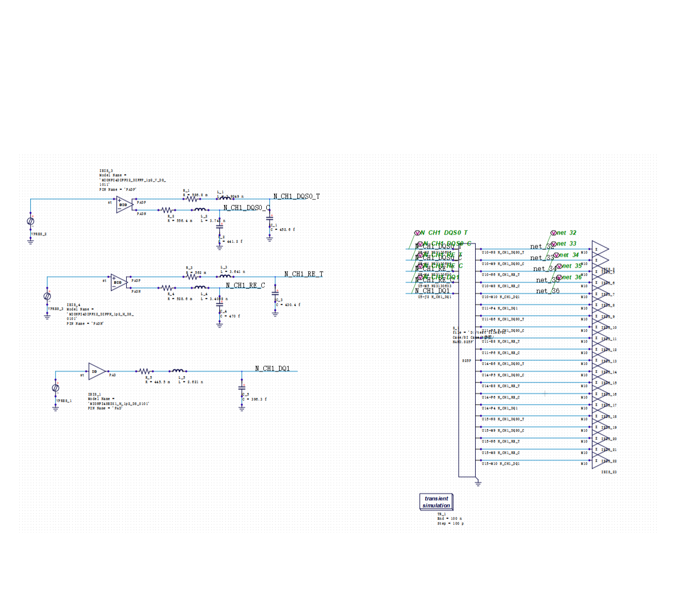
I. Schematic Setup
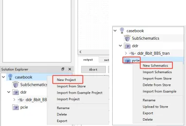
1. Create a New Project & Schematic
In your solution, right-click to select New Project. Once created, right-click again to select New Schematics. Double-click the new schematic to enter the editing mode.
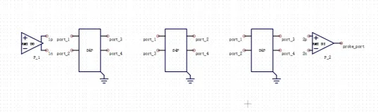
2. Component Placement & Configuration
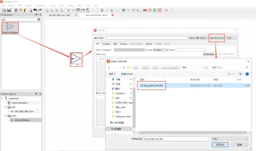
Navigate to the Component library, search for the required blocks (AMI, SNP, Channel Sim, Probe Eye), and drag them onto the canvas. Double-click each block to configure the following settings:
A. AMI (TX & RX) Configuration:
1.Import: Load the .ibs file.
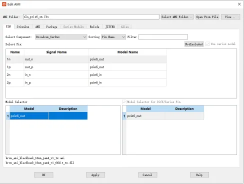
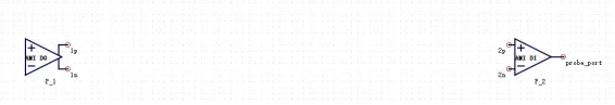
2.Select Model: In the PIN tab, select the differential output pins (e.g., 1n, 1p) and assign the corresponding PCIe 6.0 model.
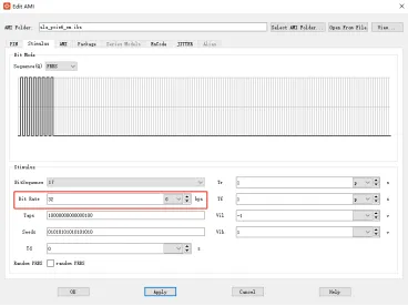
3. Stimulus: In the Stimulus tab, set the data rate (e.g., 32 Gbps).
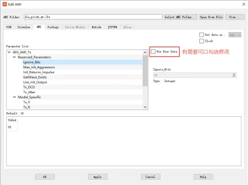
4. AMI Parameters: In the AMI tab, select parameters and check "Use User Data" to customize settings if needed.
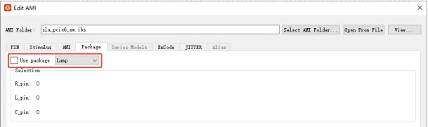
5. Package Models: If external package models are used, disable the internal IBIS package parameters.
6. RX Setup: Repeat the process for the RX model using the designated PCIe 6.0 input models.
B. S-Parameter Configuration:
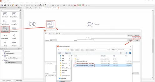
1. Import: Select the S-Parameter component, double-click to open, and use "Open from File" to load the .s4p file.
2. Preview: Click Check to preview amplitude and phase curves.
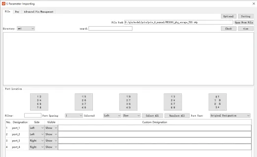
3. Port Mapping: Use Port Location to quickly arrange ports or toggle show/hide visibility for individual ports. Repeat these steps for Package and PCB Channel models.
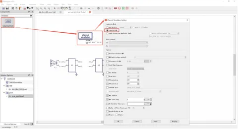
C. Channel Simulation & Probing:
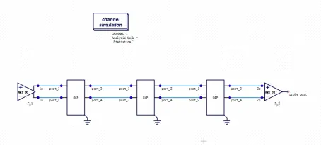
Channel Sim: Search for "Channel" in the library, drag the Channel Sim component onto the schematic, and set it to Statistical Eye Diagram mode.
. Wiring: Use the Wire tool to connect components logically from TX to RX.
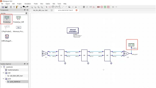
- Probe Eye: Search for "Probe," drag it to the schematic, and place it at the RX terminal for measurement.
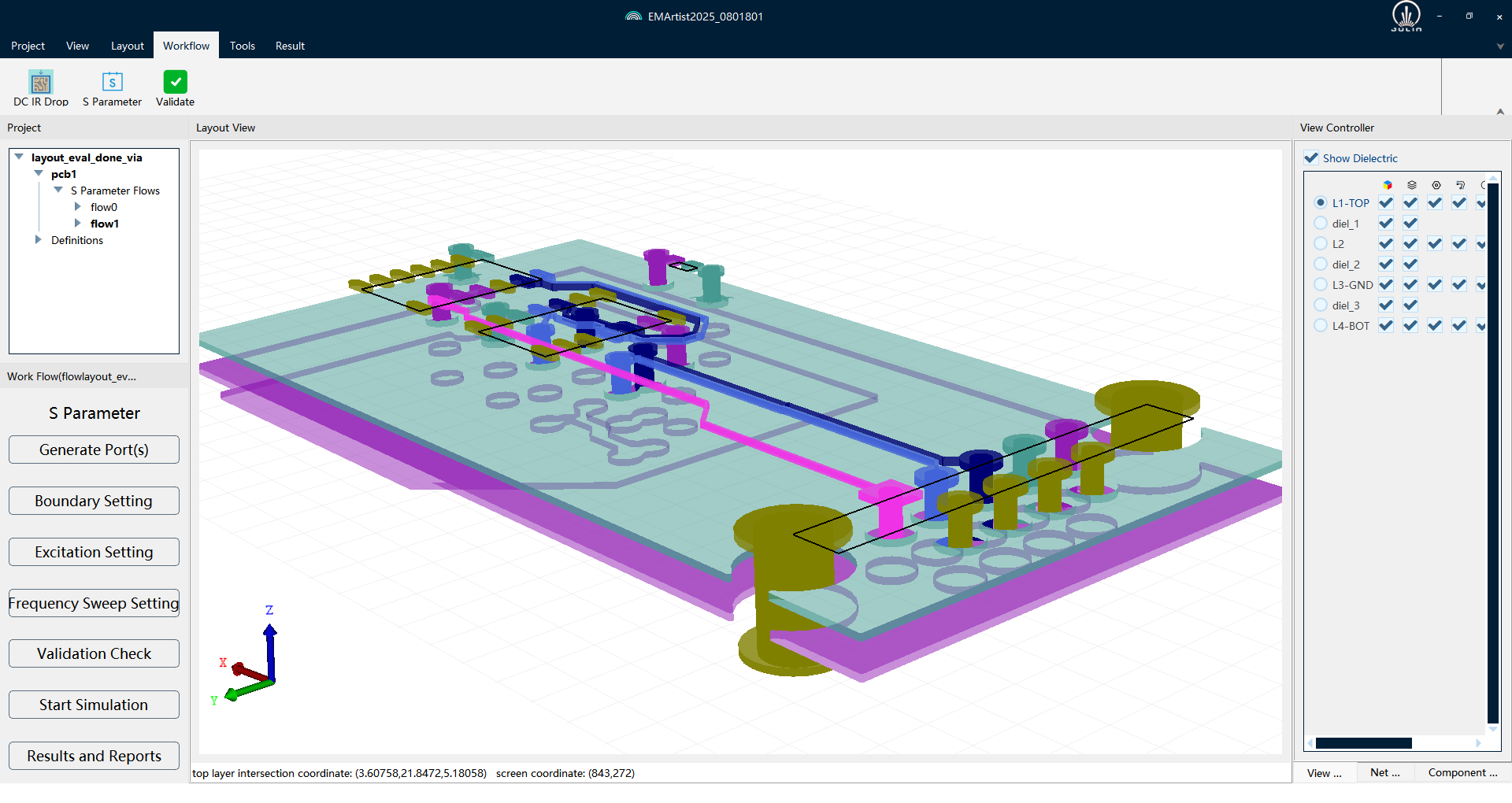
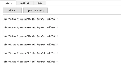
II. Running the Simulation
Click the Simulation button (gear icon) in the top menu bar to initiate the run. You can monitor the real-time simulation logs in the Output window at the bottom of the interface; click Abort if you need to cancel the process.

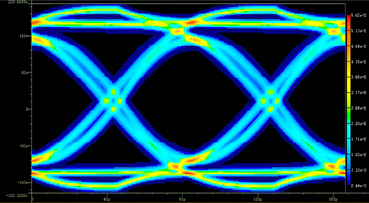
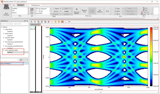
III. Viewing Results & Measurements
Once the simulation is complete, the Waveform Viewer will launch automatically.
Display: Double-click the waveform to open it in the viewer.
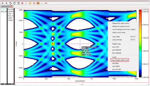
Measurement: Right-click within the waveform window and select Eye Height/Width Max to calculate the maximum eye height and width precisely.


Recommended
-
 Optimizing DDR Signal Integrity: Using DFQ Sensitivity Analysis (S1/ST) to Identify High-Leverage Design Variables
 2026.06.10
 -
 Efficiency Bottleneck in DDR5 Multi-Corner Timing Verification: PDA Analysis Methods
2026.05.27
Efficiency Bottleneck in DDR5 Multi-Corner Timing Verification: PDA Analysis Methods
2026.05.27 -
 The Mass Production Yield Trap After DDR5 SI Sign-off: Using DFQ to Predict Defect Rates Early
2026.05.07
The Mass Production Yield Trap After DDR5 SI Sign-off: Using DFQ to Predict Defect Rates Early
2026.05.07 -
 Selecting SI Simulation Tools: Practical Verification of SIDesigner's 4 Core Capabilities
2026.04.29
Selecting SI Simulation Tools: Practical Verification of SIDesigner's 4 Core Capabilities
2026.04.29