


Group Delay: The Invisible Guardian of Signal Transmission
-
 2025.07.03
In high-speed digital communication and RF systems, signals encounter various forms of distortion and aberration as they travel from the transmitter to the receiver. Group Delay is a critical parameter for describing system phase linearity and directly impacts signal fidelity and system performance. This article provides a clear introduction to the concept of group delay, its application scenarios, and its practical importance through simulation examples.
I. Definition and Physical Significance of Group Delay
Group Delay describes the variation in the time required for a signal to pass through a system relative to its frequency. It is defined as the negative derivative of the phase response with respect to the angular frequency.
The mathematical expression is:
gd = -d(phase)/dω
Where:
·gd : represents group delay (measured in seconds).
·phase : is the system's phase response.
·ω : is the angular frequency (rad/s).
The Physical Meaning
Group delay can be understood as the "travel time" of a multi-frequency signal as it passes through a system. Ideally, the delay time should be identical for all frequency components (constant group delay), ensuring all signal components reach the receiver simultaneously and maintain the original waveform. If group delay varies with frequency, different frequency components will arrive at different times, resulting in signal distortion.
In engineering practice, tools like Julin SIDesigner obtain group delay values by calculating the derivative of the complex logarithm relative to frequency, specifically by measuring the negative derivative of phase changes.
Scope of Application
1. Communication System Design: In broadband systems like 5G and optical fiber communications, group delay directly affects signal quality. Non-constant group delay leads to Inter-Symbol Interference (ISI) and increases bit error rates. Engineers must optimize filters and amplifiers to minimize group delay fluctuations across the passband.
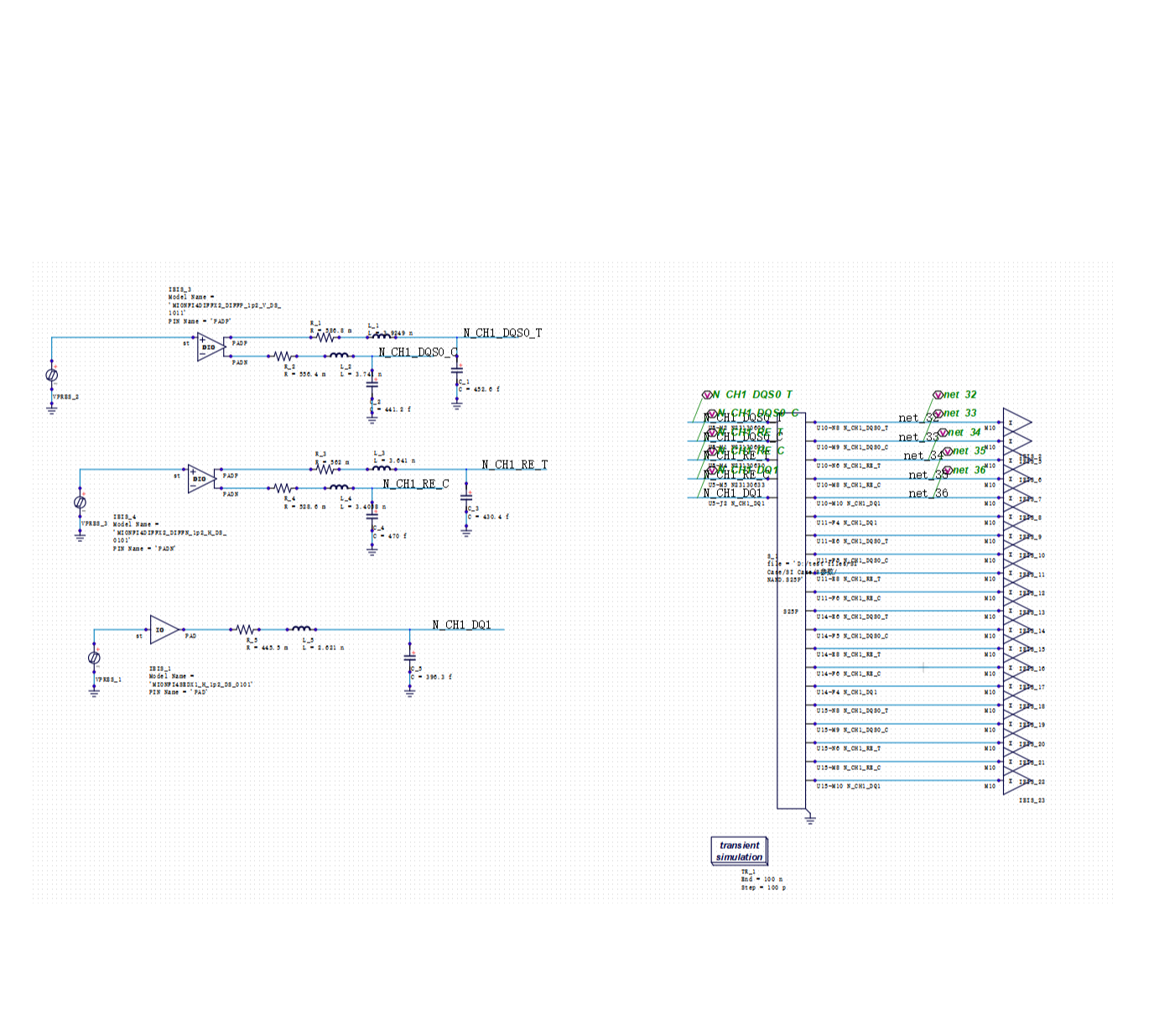
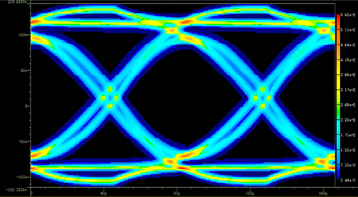
2. High-Speed Digital Circuits: At the PCB level, transmission lines, vias, and connectors all introduce group delay variations. For example, DDR memory buses have strict timing requirements; inconsistent group delay can lead to setup/hold time violations. SIDesigner allows for group delay simulation to identify potential signal integrity issues early.
3. RF and Microwave Circuits: In RF circuits such as mixers and amplifiers, group delay fluctuations cause phase distortion, affecting the constellation diagram of modulated signals. In systems like phased-array radars, group delay consistency is vital for beamforming quality.
4. Audio Processing Systems: High-end audio equipment requires flat group delay within the audible range (20Hz - 20kHz). Otherwise, different frequency components become desynchronized, causing "phase distortion" that degrades sound quality.
II. Simulation Instance Analysis
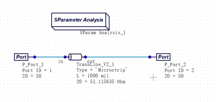
Case 1: Transmission Line Simulation in SIDesigner
During Signal Integrity (SI) simulations in SIDesigner, group delay characteristics can be obtained directly during S-parameter analysis.
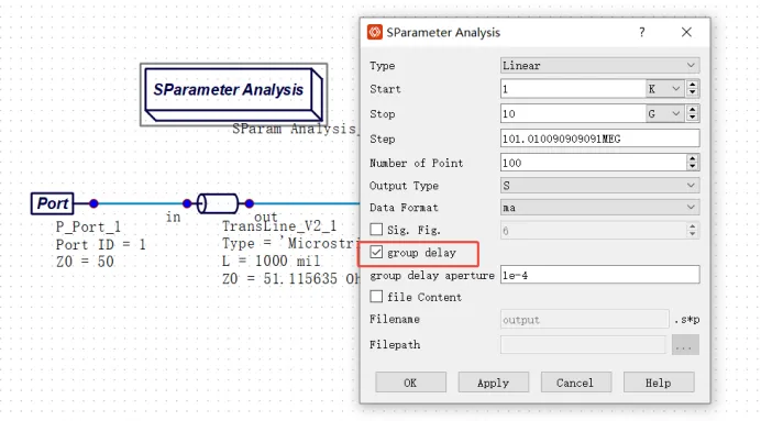
The process involves:
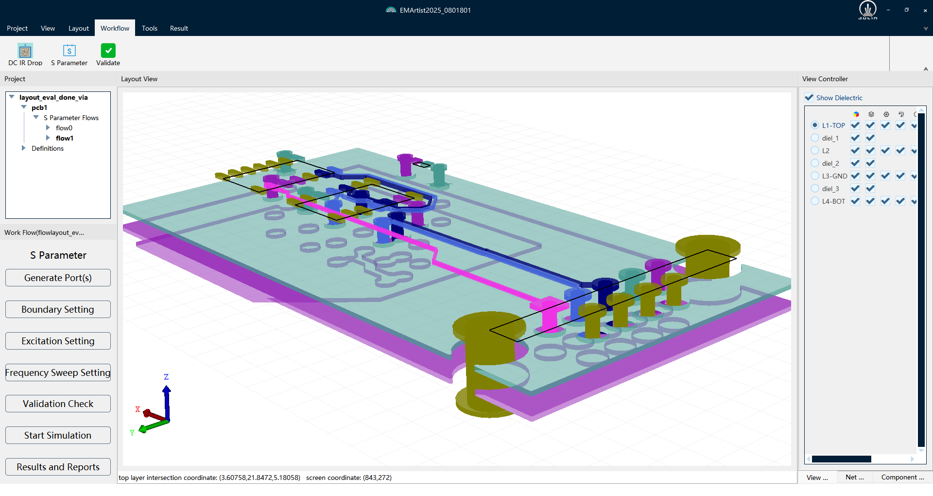
1. Creating a PCB model containing transmission lines.
2. Using S-parameter simulation tools to extract parameters.
3. Selecting the "group delay" option in the S-parameter simulation controller. SIDesigner will then extract both S-parameters and group delay information simultaneously.
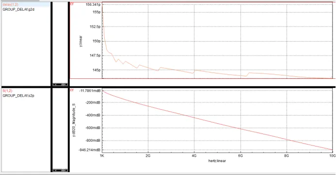
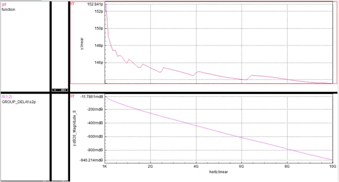
Case 2: Calculation in SIDesigner Waveform Viewer
The SIDesigner waveform viewer provides specialized analysis functions for S-parameters. By using the formula gd=group_delay('S(1,2)') in the data display window, S-parameters can be converted into group delay information.
III. Optimization and Practical Recommendations
To manage group delay effectively, engineers should consider the following:
1. Phase Linearization: Use all-pass filters or digital equalization techniques to compensate for non-linear phase responses.
2. Transmission Line Design: Optimize group delay by adjusting the PCB stack-up structure, including dielectric constants and thickness.
3. Component Selection: Choose active devices, such as filters and amplifiers, that exhibit superior group delay characteristics.
4. System-Level Simulation: Perform end-to-end simulations on platforms like SIDesigner to consider the group delay contributions of all modules comprehensively.
5. Testing and Verification: Use a Vector Network Analyzer (VNA) to measure actual group delay and compare it with simulation results.
Conclusion
As a vital parameter characterizing system phase, group delay is widely applied in high-speed digital design, communication systems, and audio engineering. By leveraging Julin SIDesigner for simulation and analysis, engineers can predict and optimize group delay during the design phase, preventing performance degradation caused by phase distortion. As signal rates continue to rise, controlling this "invisible guardian" becomes increasingly essential to ensure every data bit arrives exactly on time.
Software Trial: Feel free to click [Software Trial] to apply for a trial of our tools. For any questions during the process, please contact our support technical staff. We look forward to communicating with you!


Recommended
-
 Optimizing DDR Signal Integrity: Using DFQ Sensitivity Analysis (S1/ST) to Identify High-Leverage Design Variables
 2026.06.10
 -
 Efficiency Bottleneck in DDR5 Multi-Corner Timing Verification: PDA Analysis Methods
2026.05.27
Efficiency Bottleneck in DDR5 Multi-Corner Timing Verification: PDA Analysis Methods
2026.05.27 -
 The Mass Production Yield Trap After DDR5 SI Sign-off: Using DFQ to Predict Defect Rates Early
2026.05.07
The Mass Production Yield Trap After DDR5 SI Sign-off: Using DFQ to Predict Defect Rates Early
2026.05.07 -
 Selecting SI Simulation Tools: Practical Verification of SIDesigner's 4 Core Capabilities
2026.04.29
Selecting SI Simulation Tools: Practical Verification of SIDesigner's 4 Core Capabilities
2026.04.29