


How to Choose DDR5/HBM3 Signal Integrity Simulation Tools? Four Verification Standards
-
 2026.04.23
In our previous article, we analyzed four systemic failures in high-speed interface simulation: insufficient IBIS macro-model accuracy, cumulative errors in hierarchical simulation, lack of consensus on Signoff methodology, and fragmented tool flows.
After reading it, many engineers' first reaction was: "Should I switch tools?"
This is a reasonable question. However, "how to evaluate whether an SI simulation tool is adequate" is itself a trap-prone area.
The evaluation method used by many teams is to run a familiar case; if the results don’t show major deviations, it passes. The problem is that the four failures mentioned above do not manifest themselves in simple scenarios at all. It is precisely with more complex topologies and more extreme operating conditions that a tool's true capabilities can be tested.
This article provides an evaluation framework that directly maps those four failures to four verification standards.
The Four Failures Correspond to Four Verification Standards

Standard 1: Does the tool have a higher-accuracy alternative path?
The essence of IBIS macro-models is an approximation of chip I/O behavior. In the speed range of DDR5 and HBM3, this approximation error might already exceed the design margin itself.
This is not to say that IBIS has no value—it is completely sufficient for most conventional scenarios. The problem arises when the simulation results are at the edge of the margin; you need a higher-accuracy path to confirm the conclusion, rather than having to continue trusting this approximation.
Key Judgment: When results are on the edge of the margin or in extreme PVT corners, can the tool switch to transistor-level simulation for accuracy verification?
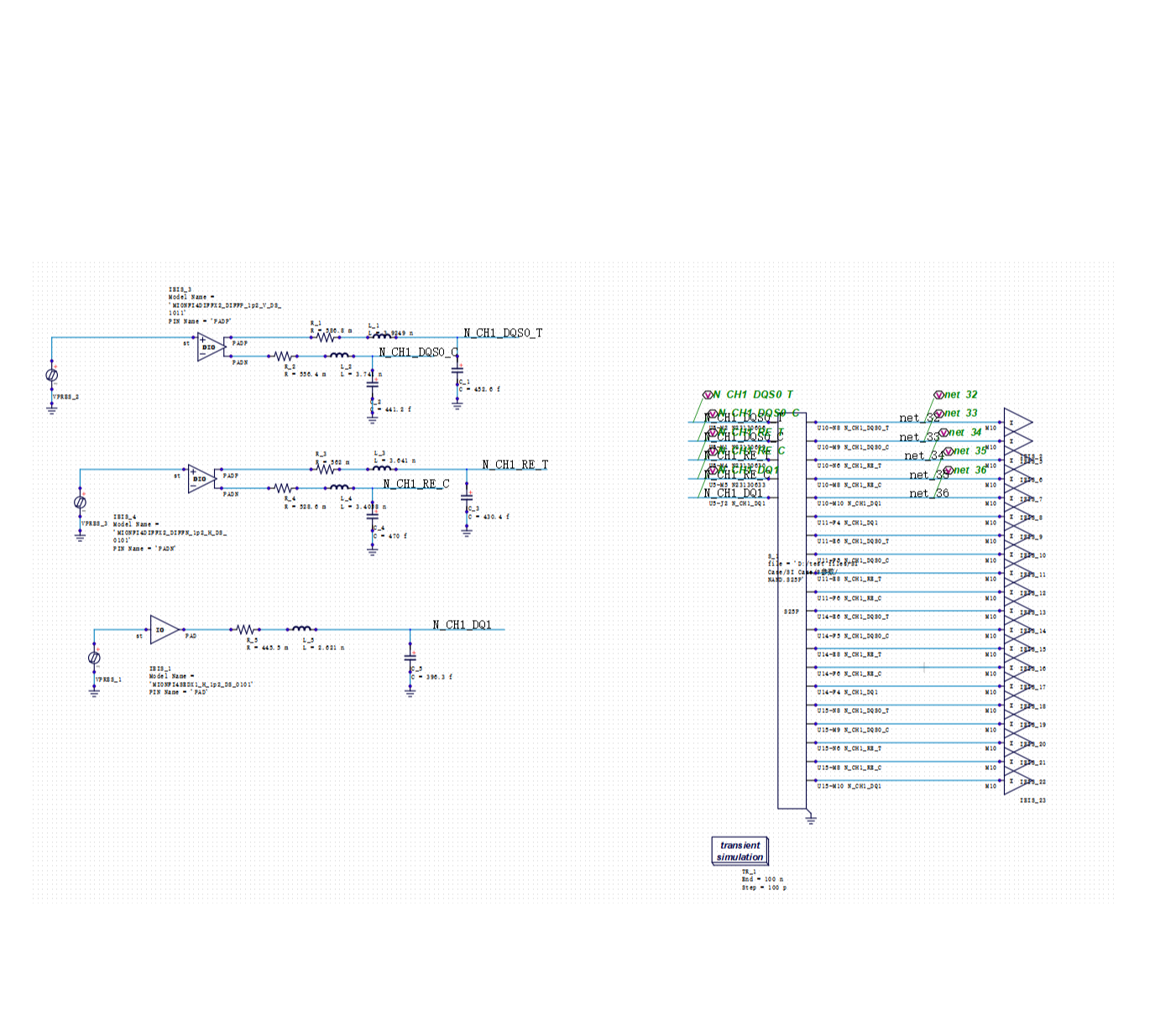
Standard 2: Can the chip-package-board level be simulated within the same environment?
The problem with hierarchical simulation is not that a single layer is modeled incorrectly, but that the coupling effects between layers are lost when they are modeled separately. The interaction between package parasitic inductance and chip I/O driving capability, or the reflections produced at package pins by PCB impedance discontinuities—these are system-level details that vanish after hierarchization.
·"Every layer passed simulation individually, but they don't satisfy timing when combined"—this situation is becoming increasingly common in DDR5 and HBM projects, and this is the root cause.
Key Judgment: Can the tool, in the same simulation environment, concurrently include the chip I/O models, package parasitic parameters, and PCB transmission lines, rather than running them separately and then overlaying the results?
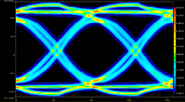
Standard 3: Are both statistical and transient methods supported?
Among the four standards, this one is the most debated and has the most concrete data to illustrate.
The statistical method (Channel Simulation) is fast, but its algorithm is built on the assumption of linear superposition. With the introduction of DFE (Decision Feedback Equalization) in DDR5, the DFE's feedback mechanism breaks this assumption. The accuracy of the statistical method systematically degrades in DFE scenarios, and this deviation is rooted at the algorithmic level, not a matter of how well the tool is implemented.
Actual verification data can illustrate the magnitude of this gap. For the same DDR interface, the calculated eye width results using three different methods:

The statistical method is 28% lower than the transient baseline. This is not a small deviation—it is sufficient to cause the Signoff conclusion to flip from "pass" to "fail."
This is not to say that the statistical method should be obsolete. For normal operating conditions and rapid iteration scenarios, its efficiency advantage is irreplaceable. The problem is: a tool with only statistical methods has no accuracy safety net for non-linear scenarios like DFE; a tool with only transient methods has engineering efficiency that is unacceptable.
Key Judgment: Does the tool simultaneously support both paths and allow for switching and comparison between the two?
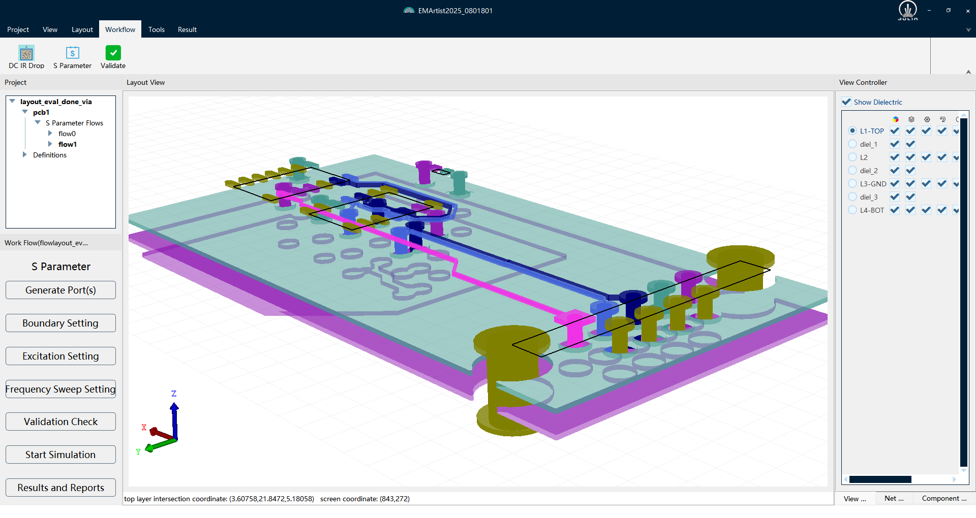
Standard 4: Can the full flow be completed within a single platform?
The cost of tool fragmentation is two-fold:
First, there is the efficiency loss, which is visible. Using Tool A for channel simulation, Tool B for transient, and Tool C for viewing waveforms and measuring eye diagrams involves repetitive importing and exporting. An analysis that could be completed in a few hours might take a whole day.
Second, there is the error introduction, which is hidden. When data is passed between tools, inconsistencies in format conversion and parameter settings itself introduce deviation. Sometimes engineers believe they have found a design problem when, in fact, it is a tool integration issue.
Key Judgment: From channel simulation to eye diagram post-processing, and from batch parameter sweeping to result reporting, can the entire workflow be completed within the same platform without needing to switch tools?
Why DOE/RSM is the Best Comprehensive Stress Test
If tested individually, each of the four standards can be passed with relatively simple cases.
However, DOE (Design of Experiments) / RSM (Response Surface Methodology) is a scenario that stresses all four standards simultaneously:
·Batch parameter sweeping requires stable eye diagram accuracy under complex scenarios (Standard 3).
·The reliability of multi-parameter sweep conclusions relies on the completeness of system-level simulation (Standard 2).
·Performing hundreds of simulations must be achievable within a single platform to be realistic (Standard 4).
·The modeling error from every simulation is amplified by the RSM modeling into the final optimization conclusion (Standard 1).
A tool that can reliably support DOE/RSM basically means it passes in all four dimensions simultaneously.
Actual data can illustrate how much design improvement reliable DOE/RSM can bring. A real project from a leading memory chip company: simultaneously scanning multiple key parameters such as vddq, cpu_odt, and dram_odt, establishing a high-accuracy predictive model through RSM, combined with sensitivity analysis to isolate the most sensitive design variables, and finally performing collaborative optimization of performance and yield.

Results before and after optimization:

The defect rate dropped from 13.8% to 7.6%, a nearly 50% decrease—with almost no loss in eye height and width. The yield improvement came entirely from systemic optimization within the parameter space.
This result did not rely on tuning experience, but on having simulation accuracy × batch capability × flow integration all in place at once.
A Practical Suggestion
The verification methods for the four standards differ:
For Standards 1 and 2, separate verification scenarios are needed:
·Take a real case with a very tight margin and see if the tool can switch to a higher-accuracy path for a second confirmation (Standard 1).
·Attempt to put the chip I/O model, package S-parameters, and PCB transmission lines in the same simulation environment—see if it can be done, and how large the gap is between the result and that of overlaid separate simulations (Standard 2).
For Standards 3 and 4, directly use the most complex DOE requirements from a project to test:
·Can the batch simulation run to completion without errors (Standard 4)?
·Are the statistical eye diagram results reasonable when DFE parameters are at extreme values (Standard 3)?
·Can the entire flow be navigated without switching tools (Standard 4)?
If it passes, then we can talk about other things; if it fails, any single point of accuracy advantage is in vain.
Is there a tool on the market that simultaneously passes all four standards? Let's verify in the next article.


Recommended
-
 Optimizing DDR Signal Integrity: Using DFQ Sensitivity Analysis (S1/ST) to Identify High-Leverage Design Variables
 2026.06.10
 -
 Efficiency Bottleneck in DDR5 Multi-Corner Timing Verification: PDA Analysis Methods
2026.05.27
Efficiency Bottleneck in DDR5 Multi-Corner Timing Verification: PDA Analysis Methods
2026.05.27 -
 The Mass Production Yield Trap After DDR5 SI Sign-off: Using DFQ to Predict Defect Rates Early
2026.05.07
The Mass Production Yield Trap After DDR5 SI Sign-off: Using DFQ to Predict Defect Rates Early
2026.05.07 -
 Selecting SI Simulation Tools: Practical Verification of SIDesigner's 4 Core Capabilities
2026.04.29
Selecting SI Simulation Tools: Practical Verification of SIDesigner's 4 Core Capabilities
2026.04.29